The Art of Material Selection in High-Performance Hydraulic Valve Machining
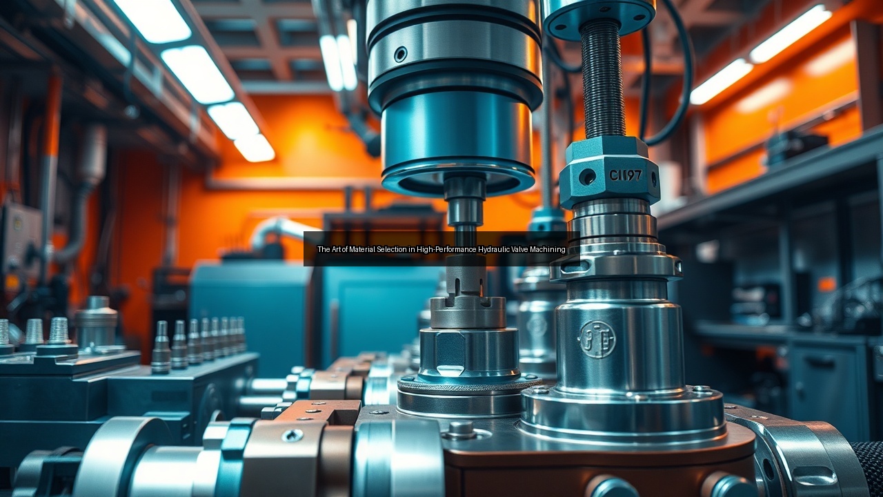
Understanding Material Selection for Hydraulic Valve Machining
Importance of Material Properties
Engineers prioritize material properties when they approach hydraulic valve machining because strength, corrosion resistance, and thermal stability directly determine how well a valve performs under pressure. Hydraulic systems in automotive and industrial settings demand metals that withstand repeated cycles without deforming. Material selection influences everything from spool movement to manifold integrity. Hardness affects tool wear during machining, while ductility prevents cracking when operators apply high torque. Manufacturers evaluate wear resistance to extend service life in dirty or high-temperature environments. They test conductivity for applications where heat dissipation matters. Proper material selection reduces failure rates and keeps hydraulic valves reliable across demanding operations. In addition, properties such as fatigue resistance become critical in applications involving millions of pressure cycles, where even minor microstructural flaws can propagate into cracks. Yield strength and ultimate tensile strength guide the minimum wall thicknesses required to contain system pressures that often exceed 350 bar. Thermal conductivity also plays a role in high-flow valves, allowing rapid heat transfer away from throttling orifices to prevent localized overheating that could degrade seals or hydraulic fluid. By quantifying these interrelated characteristics through standardized testing protocols such as ASTM or ISO specifications, engineers create a reliable foundation for both performance predictions and cost-effective production planning.
Common Materials Used in Hydraulic Valves
Stainless steel dominates hydraulic valve machining because it resists corrosion and maintains dimensional stability during drilling and milling. Aluminum alloys offer lighter weight for mobile hydraulics while still supporting tight tolerances. Brass appears in low-pressure valves where machinability speeds production. Cast iron provides excellent damping in large manifold blocks. Titanium suits aerospace hydraulics that face extreme conditions. Manufacturers often combine these metals through casting followed by precision machining to create hybrid components. Each choice aligns with the specific hydraulic valve design, ensuring spools slide smoothly and seals maintain pressure without leaks. Beyond these staples, duplex stainless steels offer enhanced pitting resistance in marine or offshore environments, while precipitation-hardening grades deliver higher strength after heat treatment without sacrificing corrosion performance. Aluminum alloys such as 7075 provide superior strength-to-weight ratios for aerospace manifolds when anodized for surface protection. Brass formulations containing lead-free additives meet modern environmental regulations while retaining the free-cutting characteristics that reduce cycle times. Cast irons with nodular graphite microstructures improve both damping and tensile properties, making them suitable for large stationary valves subjected to vibration. Titanium alloys, though costly, enable weight savings of up to 40 percent in flight-control actuators where every kilogram matters. Hybrid constructions, such as stainless-steel inserts pressed into aluminum bodies, combine the best attributes of multiple materials while optimizing overall component mass and cost.
Impact of Material on Machining Processes
Material choice alters every step of hydraulic valve machining. Harder metals require slower feeds during milling to avoid tool breakage, while softer alloys allow aggressive drilling speeds. Thermal expansion rates dictate coolant strategies to preserve accuracy. Cast metals often need extra passes to remove porosity before final tolerances are met. Manufacturers adjust cutting parameters based on the metal to control burrs and achieve smooth surfaces on spool bores. Material selection therefore shapes cycle times, tool life, and overall manufacturing cost in valve production. For instance, austenitic stainless steels work-harden rapidly, necessitating positive rake angles and coated carbide inserts to maintain edge life. Aluminum alloys, by contrast, permit high-speed machining with polycrystalline diamond tooling yet demand careful chip evacuation to prevent built-up edge. Titanium's low thermal conductivity concentrates heat at the tool-chip interface, requiring high-pressure coolant delivered through the tool to extend insert life. Cast materials introduce additional variables such as graphite nodules or shrinkage porosity that can cause unexpected tool deflection if not detected by in-process probing. Consequently, process planners create material-specific databases of recommended speeds, feeds, and depths of cut that balance productivity against the risk of scrap, directly influencing quoting accuracy and delivery schedules for both prototype and series production.
Machining Techniques for High-Performance Valves
Overview of Machining Processes
Hydraulic valve machining combines several operations to transform raw metal into functional components. Turning creates cylindrical features on spools and bodies. Milling generates flat surfaces and complex ports in manifolds. Drilling produces the precise holes that direct fluid flow. Modern machines integrate these steps on multi-axis centers to reduce setups. Manufacturers rely on consistent processes to maintain the accuracy required for high-pressure hydraulics. Each operation builds on the previous one, culminating in valves that meet strict performance standards. Five-axis machining centers further enable undercuts and angled ports without repositioning, preserving datum integrity across all features. Swiss-type lathes excel at producing slender spools with length-to-diameter ratios exceeding 20:1 while holding diametral tolerances under 5 µm. Deep-hole drilling with single-lip or BTA tooling reaches depths of 300 mm or more inside manifold blocks, maintaining straightness within 0.05 mm per 100 mm. Post-machining processes such as honing or roller burnishing refine spool bores to single-digit Ra values, ensuring low-friction sliding and extended seal life. Process integration through palletized automation and in-machine probing reduces non-cut time and supports lights-out manufacturing of valve families that share common fixturing.
Drilling and Milling in Hydraulic Valve Production
Drilling creates the internal passages that control fluid direction inside hydraulic valves. Operators use specialized bits to reach deep into manifold blocks without deviation. Milling follows to refine port shapes and ensure smooth transitions that minimize turbulence. Both processes demand rigid fixturing because even slight movement ruins tolerances. Manufacturers program machines to drill pilot holes first, then enlarge them in stages. This approach prevents chatter and keeps burrs minimal. Milling then finishes sealing surfaces so spools operate without binding. The combination delivers valves that handle high flow rates reliably. Peck-drilling cycles with controlled retracts evacuate chips from deep cross-holes, while orbital drilling techniques reduce thrust forces and improve hole cylindricity in thin-walled sections. Milling strategies such as trochoidal tool paths maintain constant chip load even when machining tough stainless steels, extending tool life by 30–50 percent compared with conventional slotting. Fixture design incorporates hydraulic clamping and locating pins that repeat within 2 µm, allowing multiple setups across different machine tools without loss of reference. By sequencing operations from roughing through semi-finishing to finishing, manufacturers control residual stresses and achieve the sub-micron form tolerances required for pressure-compensated flow sections.
Achieving Precision with CAD Technology
CAD software drives precision in hydraulic valve machining by allowing engineers to model every feature before metal is cut. Designers simulate spool movement and fluid paths to verify function. The digital model transfers directly to CNC machines, eliminating manual calculations. CAD also helps optimize tool paths for drilling and milling, reducing cycle time while preserving accuracy. Manufacturers update designs quickly when new hydraulic requirements emerge. This technology ensures that complex manifold geometries remain manufacturable and that final valves match the intended structure exactly. Modern CAD packages incorporate computational fluid dynamics modules that predict pressure drop and cavitation risk within internal galleries, enabling early geometry adjustments. Feature-based modeling automatically generates manufacturing drawings with GD&T callouts that align with CNC post-processors, reducing transcription errors. Digital twins of both the valve and the machine tool allow virtual collision detection and cycle-time estimation before any metal is cut. When customer specifications change, parametric models propagate updates through the entire bill of materials and tool-path library, shortening engineering change lead times from days to hours while maintaining traceability for quality audits.
Addressing Challenges in Hydraulic Valve Manufacturing
Managing Burrs and Surface Finish
Burrs form during drilling and milling of hydraulic valves and must be removed to prevent spool damage or seal failure. Manufacturers employ deburring tools and abrasive flow processes to clean internal passages. Surface finish directly affects leakage rates, so they polish critical bores to specific roughness values. Material selection influences burr formation; ductile metals create longer strings while brittle ones fracture into small chips. Consistent management of burrs during hydraulic valve machining keeps production moving and maintains valve performance under pressure. Thermal deburring in a controlled oxygen-rich chamber removes internal burrs inaccessible to mechanical tools, while abrasive-flow machining with polymer media laps intersecting passages to uniform radii. Surface-finish specifications typically call for 0.2–0.4 µm Ra on spool bores and 0.8 µm Ra on sealing lands, verified by stylus or optical profilometers. In-process monitoring using acoustic emission sensors detects burr breakthrough events, triggering adaptive feed reductions that minimize secondary operations and maintain takt time.
Accuracy and Tolerances in Valve Machining
Accuracy defines success in hydraulic valve machining because even micron-level deviations cause leaks or sluggish response. Manufacturers hold spool-to-bore clearances within tight tolerances to guarantee smooth operation. They use coordinate measuring machines during inspection to verify dimensions after each major operation. Temperature control during machining prevents expansion that would shift tolerances. Material selection plays a role since different metals respond uniquely to cutting forces. Maintaining these standards across batches ensures every valve meets hydraulic system requirements. Typical diametral clearances range from 2–8 µm depending on valve size and pressure rating, with cylindricity held to 1 µm over 100 mm lengths. Climate-controlled shops maintain 20 °C ± 0.5 °C, and parts are allowed to stabilize before critical measurements. On-machine probing with kinematic touch triggers updates tool offsets in real time, compensating for thermal drift and tool wear without operator intervention. Statistical process control charts track key characteristics such as spool diameter and bore roundness, enabling early detection of tool wear or fixture settlement before out-of-tolerance parts are produced.
Functional Testing and Quality Inspection
Functional testing confirms that machined hydraulic valves perform as designed before shipment. Technicians pressurize each unit and cycle the spool to check for leaks and response time. Quality inspection includes dimensional checks, surface analysis, and material verification. Manufacturers document results to trace any issues back to specific machining steps. This rigorous process catches problems early and protects downstream hydraulic systems in automotive and industrial applications. Thorough testing builds customer confidence in the finished valves. Production leak-test stands apply pressures up to 1.5× working pressure while monitoring for bubble formation or pressure decay over 30–60 seconds. Dynamic response testing records spool shift times under varying pilot pressures and temperatures, comparing results against design simulations. Material certificates from the mill are cross-referenced with ultrasonic or eddy-current inspections performed on incoming bar stock, ensuring freedom from inclusions that could initiate fatigue cracks. All data are archived in a digital quality record linked to the part serial number, supporting full traceability required by automotive and aerospace customers.
Prototyping and Design Considerations
The Role of Prototyping in Valve Development
Prototyping accelerates hydraulic valve development by letting manufacturers test designs before full production. Engineers machine initial prototypes from the selected material to evaluate fit and function. They run these samples through functional testing to measure flow characteristics and pressure drop. Feedback from prototype valves guides adjustments to spool geometry or manifold layout. Rapid iteration reduces time to market and avoids costly changes later. Material selection is validated at this stage to confirm it supports both performance and machinability goals. Additive-manufactured plastic models provide early visualization of complex internal passages, while metal prototypes produced on the same five-axis platforms intended for series production reveal real-world machinability issues. Instrumented test rigs capture pressure, flow, and temperature data at multiple points, allowing direct comparison with CFD predictions. Lessons learned during prototype iterations frequently lead to revised casting designs that reduce subsequent machining stock allowances and shorten overall lead times.
Designing for Manufacturability
Designing for manufacturability ensures hydraulic valve machining remains efficient from the first concept. Engineers simplify internal passages to reduce drilling complexity. They specify standard tool sizes for milling operations to avoid custom cutters. Material selection considers how easily the metal yields to machining without excessive burrs. Draft angles on cast features ease removal from molds. These decisions lower scrap rates and shorten cycle times while preserving the accuracy and tolerances required for reliable hydraulic valves. Design rules limit minimum wall thickness to three times the drill diameter for intersecting holes and mandate generous radii at all reentrant corners to reduce stress concentrations and improve chip evacuation. Standardizing port threads and O-ring grooves across product families allows reuse of form tools and inspection fixtures. Early involvement of manufacturing engineers during the design review stage identifies potential fixturing challenges and recommends datum schemes that remain accessible throughout all operations.
Integrating Structure and Function in Valve Design
Successful valve design merges structural integrity with hydraulic function. Engineers position ports to minimize stress concentrations in the manifold while maintaining optimal flow paths. Spool geometry must balance sealing requirements against ease of machining. Material selection supports this integration by providing the strength needed for high-pressure operation without adding unnecessary weight. Manufacturers review every feature for both performance and production feasibility. The result is a valve that operates precisely and withstands the rigors of continuous hydraulic service. Finite-element analysis validates that fatigue life exceeds one million cycles under worst-case pressure spikes, while topology optimization routines remove non-load-bearing material to reduce weight without compromising safety factors. Concurrent engineering sessions align spool land widths with standard grinding wheel diameters and ensure that all sealing surfaces remain reachable by standard honing mandrels. The outcome is a robust, cost-effective valve whose geometry satisfies both the hydraulic circuit requirements and the practical constraints of precision machining.
See Also
- Achieving Flawless Accuracy in Hydraulic Valve Machining Through Advanced Inspection
- Mastering Hydraulic Valve Machining Techniques for Precision Manufacturing
- Exploring the Role of Functional Testing in Hydraulic Valve Machining Quality Assurance
- Innovative CAD Solutions Transforming Hydraulic Valve Design and Machining